
Owners Manual
FETroller.2
Standard (voltage Reduction)
and
E-Wire
Choke models
Fully Electronic Controller with 3rd Eye’s exclusively designed
“All FET Design” Motor Drive “FETDrive” and Brakes “FETBrakes”
“Selectable Throttle Curve Controls” Cooling Fan, No Fuses Required
VR Model -- Electronic Choke with, On/Off Switch and (FTB) Bypass
E-Wire Model -- Electronic Wire Choke with On/Off and 3-20Ft Switch and 20-30ft Switch
Keep Precision Resistor Clean (using a DRY Q-Tip)!
Hooking
Up the FETroller.2
o
The FETroller.2 is ONLY for use on
tracks wired for POSITIVE POLARITY (brake wired to
“-“ side of battery). Verify
the polarity of the track prior to use.
DO
NOT attempt to connect the FETroller.2 to a
track wired for negative polarity or to Drag or HO tracks.
o
ALL
power leads must be connected to the correct colored terminals.
Failure to do so may cause unnecessary tripping of re-settable fuses
and reduce the life of the FETroller.2.
o
When connecting the power leads,
ALWAYS connect the Red power lead first!
The Red lead must remain
connected at all times. In the event the lead is not hooked up, the
FETroller.2 will supply full power and the car will take off.
o Once the controller is hooked up, verify the FETtroller.2 has power – the blue LED should be on/visible.
WARNING
ABSOLOUTLY
NO EXCEPTIONS
- Third Eye Technology has taken reasonable
measures to prevent FETroller.2 damage in the event of polarity reversal
with resettable fuses. However,
Third Eye Technology
does not warrant the FETROLLER.2 against
abusive and/or repeated intentional polarity reversal.
It is important to ensure the FETROLLER.2 is hooked up correctly at all
times.
Sensitivity Adjustment (Blue Control Knob)
o
The blue
knob is the
Sensitivity adjustment. Turn the knob
clockwise for less sensitivity, and
counter-clockwise for greater sensitivity.
o
A cluster of 4 small “DIP” (slide) switches is located on the side of the
handle – these are
Throttle Curve Switches. Setting a
switch in the up position softens the bottom portion of the throttle curve.
The switches have an additive effect - they all have the same weight and can
be set in any order. Setting
all four (4) switches in the up position will result in the “softest”
throttle curve.
o
(Option) The red “Mush” Button located at front of the handle when pressed,
decreases the Sensitivity to minimum regardless of the sensitivity setting
to allow cars to roll through glue.
Brake Adjustment (Red Control Knob)
-
The red knob is the Brake adjustment.
-
Turn the knob clockwise for less Braking effect (car will “roll” further before coming to a complete stop)
-
Turn the knob counter-clockwise for greater Braking effect (car will “roll” less before coming to a complete stop)
4 position Dip Switches
A cluster of 4 slide switches located on the side of the handle is the
Throttle
Curve Switches. Setting a switch in the up position softens the
bottom portion of the throttle curve. The switches effects are additive,
they all have the same weight and be set in any order, with all 4 switch up
has 4 times the effect.
Electronic Voltage Reduction Choke Control (Yellow Knob)
o
The Electronic Choke Control provides racers with additional adjustments to
fine-tune FETroller.2 behavior.
o
The Choke On/Off Switch in the down position turns the Choke Off. When the
switch is in the up position, the Choke is On.
o
The
Yellow knob is used to adjust the Choke (voltage reduction).
§
When the Choke On/Off switch is in the ON (up) position, turning the
Yellow
knob clockwise will reduce the amount of battery voltage which the
controller passes to the track
§
When the Choke On/Off switch is in the ON (up) position, the Full Throttle
Bypass (FTB) switch described below will further determine how the Choke
behaves
o
The Choke FTB Switch (Full Throttle Bypass) works in conjunction with the
Choke On/Off switch. The Choke
On/Off switch must be in the ON (down) position for the FTB Switch to have
any effect.
§
When the FTB Switch is in the down position (FTB OFF), the
Yellow
knob adjustment is in effect at all times.
For example, if you’ve used the
Yellow
knob to dial out some track voltage, the reduction is in effect around the
entire track (even on the straights).
§
When the FTB Switch is in the up position (FTB ON), the
Yellow
knob adjustment is ONLY in effect when the controller is NOT at full
throttle. When the controller
is at full throttle, the Choke setting is “bypassed” and full battery power
is passed to the track. This
setting is particularly helpful if you want to dial out some track voltage
to improve performance in corners or technical sections but still want full
power/speed when at full throttle (e.g. straight sections).
E-Wire Electronic Wire Choke (Green
Knob)
o
When the Choke switch is in the ON (up) position the choke is initially set
to 3-20ft
o
The
Green Knob is used to adjust the Choke Feet, , turning the
Green
knob clockwise the increase the number of Choke Feet, adding more
Choke.
o
When the Choke Switch is in the ON position and then the 40ft Switch is in
the ON (up) position the Choke operates from 20Ft-40Ft.
o
The
Green Knob is used to adjust the Choke Feet, , turning the
Green
knob clockwise the increase the number of Choke Feet, adding more Choke.
Mush Button Installation
·
The mush button is not standard and is a user installed option. Radio Shack
P/N
275-1547.
·
Using a step drill, drill a ¼ inch hole into the front of the front cover
near the throttle resistor area, allowing clearance so the button does not
make contact with other components.
·
There are 2 large pads at the back of the handle marked “Mush”.
Solder wires onto the 2 pads then connect the other wire ends to the
Mush Button.
Reverse
Polarity/Incorrect Hook-up
It is extremely importance the unit be hooked up correctly
– this is a prerequisite of being a qualified racer.
In the event the unit is hooked up incorrectly the unit will self –protect,
by the time the connections are corrected the internal fuse will reset and
operation will be normal.
If the Red Wire is not hooked up, the car will have no brakes and no full
power. If the track’s brake fuse is blown, the same condition will occur.
CARE AND MAINTENANCE
The
FETroller
2 is a precision electronic instrument and should be treated
accordingly. To ensure optimal
performance, follow the steps described below.
Do NOT:
o
Throw or misuse or abuse the FETroller2 in any way.
o
Carry the FETroller2 by the handle draped over the neck or place excessive
strain on the entire assembly.
o
Pull the power leads from the track terminals.
Always disconnect the power leads one-at-a-time by “opening” the
alligator clip.
o
Under any circumstances oil/lubricate the precision resistor or wiper
button.
o
Cut away the FETroller2 handle. The precision resistor must remain protected
from damage, dirt and debris!
o
Perform maintenance on the FETRoller2 with the power applied.
o
For any reason disassemble the Power box. There are no user serviceable
components inside.
*** Important *** Keep Precision Resistor Clean (using a DRY Q-tip)!
Maintaining the FETroller 2
*** Warning ***
- Never use solvents/cleaning fluids
other than Motor Spray
(such as PURE contact cleaner for slot cars)
to clean the Precision Resistor. Use only in extreme cases – a DRY Q-Tip
will suffice for routine cleaning.
The FETroller 2 requires minimal maintenance to achieve optimal performance:
o
Handle Hardware (Required) – Do not lose the spacer at the front of the back
cover or the #4 washer and nylon spacer that set over the trigger stop screw
at the front of the handles circuit board. If these parts are missing
“Trigger to Hang-Up” can occur due to PC board misalignment.
o
Whenever the Precision Resistor shows evidence of “tracking” (discoloration
across the face of the Precision Resistor where the Wiper Button travels),
cleaning is recommended.
o
Use a DRY
Q-tip to clean the precision resistor – move the Q-tip up/down (same
direction as resistor windings).
NEVER use any type of liquid/chemical other than motor spray!
o
Occasionally place a drop of light oil on either side of the trigger
bushing.
Trigger Arm Adjustment
Initial and
periodic maintenance is necessary
(Perform the below procedure before contacting 3rd Eye for
repairs).
##Trigger Button Break-In Period##.
Follow the below procedure:
When the trigger is new, the Trigger Button needs use to become fully seated
to provide smooth trigger action. Sometime after use the trigger will become
scratchy. When this occurs, the button will require sanding to smooth the
operation. Several sandings may be required to achieve longer-term smooth
operation.
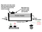
The Trigger Arm Button must remain in contact and track correctly across
Precision Resistor at all times in order to function properly. Indications
of an improperly adjusted trigger are inconsistent Trigger response or a
scratchy/rough feeling when the Trigger is pulled during various points of
throttle travel including reasonable side pressure on the Trigger
(the car stutters or is inconsistent or inoperative).
If the Button and Trigger Arm are in good condition perform the following
steps as necessary.
This function provides smooth and quiet Trigger
operation and is a critical for maximum performance.
Caution -- Use extreme care when around the throttle resistor, do not use
sharp objects, damage may occur. In the event the throttle resistor is
damaged, replacements are not available and repair by 3rd Eye
will be necessary.
1.
Remove the three (3) screws/nuts, which hold the 2 halves of the handle
together. Carefully remove the
Printed Circuit Board (PCB), which includes the Trigger assembly.
2.
With the return spring installed, Adjust the Button tension on the Precision
Resistor, by SLIGHTLY bending the Trigger Arm
near the base (where it
is already bent) to increase the tension or pulling LIGHTLY on the arm at
the button to decrease the tension. Keep in mind that the Button must
track at a slight angle with the Precision Resistor as illustrated below. If
not, use your fingers to SLIGHTLY (carefully) bend the Trigger Arm until
proper alignment is achieved.
3.
Verify that proper tension is achieved when the Trigger slides across the
Precision Resistor easily.
Also, check when the trigger is slowly released and comes to rest, it must
easily and repeatedly make contact with the Brake Stop. It may be necessary
to repeat step 1. Note: This portion of the
operation is critical.
4.
Remove the Return Spring then “Pre-seat” the Trigger Button by placing
slight pressure on the trigger button then cycling the button across the
Precision Resistor until tracking occurs on the resistor. Blow off the
tracked material.
5.
Re-connect the return spring then carefully insert a 1”x3” piece of 400-600
grit sand paper between the Precision Resistor and Button length wise to the
Resistor with the abrasive side facing toward the Button (AWAY from the
resistor).
6.
Holding the sandpaper in place and by pulling on the Trigger, cycle the
Trigger Button across the full travel of the Resistor a number of times
until the sand paper is loaded, then move the sand paper slightly and
repeat.
7.
Verify that the Trigger action is very smooth, all stops contacts and
trigger travel/alignment is correct.
8.
Check to see that under normal side thrust does not cause the Trigger Button
to lift away from the Precision Resistor.
9.
Carefully put the PCB in the Handle and re-assemble.
10.
Apply power to the FETroller 2 and verify everything is functioning
properly.
Any questions about products, repairs, or Track Sales locations contact
Third Eye Technology (Howard Smith) at (707) 664-1722 or E-mail at
I3rdeyeguy@aol.com
thirdeyetechnology.net